

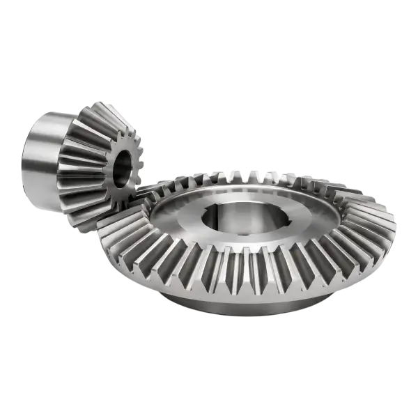
Selecting bevel gears for intersecting shafts
| Input | Associated consideration |
|---|---|
| Shaft angle and tooth counts | Conical geometry of the pair and transmission ratio |
| Tooth type and face width | Contact arrangement and loading |
| Mounting distances and reference features | Correct operating position in the housing |
| Condition of the mating gear | Compatibility of the replacement within the pair |
Considering material and mounting position together
Tooth contact loading and root stress form the basis for material and heat treatment selection. Shock loads, lubrication and continuous operating time also matter. Any finishing required after heat treatment should be planned alongside the dimensions of critical bores and end faces. Position within the housing is particularly important for bevel gears: changes in mounting distance or bearing adjustment can change tooth contact. A matching outside diameter alone therefore does not establish a compatible pair.
What should a bevel gear drawing specify?
- Tooth counts of both gears, shaft angle and the specified tooth type.
- Where module and pressure angle are defined; spiral hand and angle if applicable.
- Face width, conical geometry data and mounting distances.
- Bore or shaft dimensions, keyways, shoulders and reference surfaces.
- Material, heat treatment, hardness zones and required finishing operations.
- Operating backlash, contact requirements, mating gear data and inspection requirements.
Preparing an enquiry for one gear or a pair
Frequently Asked Questions
Are bevel gears only used on shafts at right angles?
No. Bevel gears are intended for intersecting shaft axes, and the shaft angle can vary with the design. That angle must be stated on the drawing. An offset arrangement with non-intersecting axes should not be defined as though it had the same bevel gear geometry.
Can only the pinion be replaced in a worn pair?
This depends on the wear, tooth form and mounting conditions of the mating gear. The contact pattern and backlash between the new pinion and existing component require review. Where possible, provide both gears together with mounting dimensions and information about the damage.
Why does mounting distance matter?
Mounting distance defines the operating position of a gear relative to its reference surface. A change in position can affect tooth contact and backlash. Alongside correct component geometry, the bearings, housing reference features and assembly adjustment must be considered for the pair to operate appropriately.