

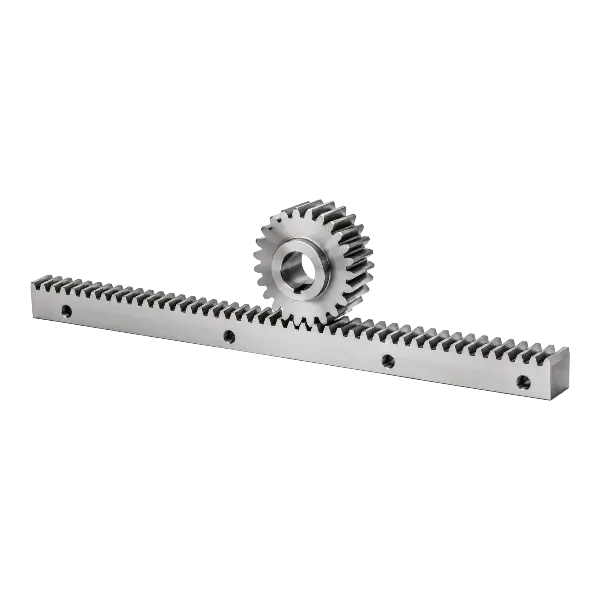
Rack and pinion for linear motion
A rack is a straight or helical toothed component that converts pinion rotation into linear motion. It is used in machine axes, handling mechanisms, gate drives and positioning systems. Achieving the required motion depends on tooth geometry, how the rack is fixed to its support and how it is positioned relative to the pinion.
- Module, pressure angle and tooth form
- Overall length, working travel and mounting section
- Pinion details, load and movement frequency
Mounting details matter as much as the teeth
The drawing should clearly show section dimensions, mounting hole positions and reference surfaces. The joint requires separate consideration where several racks are used end to end. Maintaining tooth pitch continuity across the joint and preserving alignment are important for continuous motion.
| Application topic | Required drawing information | Related selection |
|---|---|---|
| Pinion matching | Module and tooth geometry | Meshing compatibility |
| Single-piece mounting | Holes and reference surface | Fixing arrangement |
| Joined lengths | End geometry and pitch | Length alignment |
| Positioning | Backlash and inspection criteria | Mounting adjustment |
Alignment, backlash and operating load
Information for a gear rack quotation
Frequently asked questions
How are a rack and pinion matched?
Module, pressure angle and tooth form must be compatible. Helix angle and hand also affect matching in helical arrangements. Pinion diameter, motion requirements and mounting configuration are assessed together to establish the rack position within the system.
What matters when joining rack lengths?
Tooth pitch continuity and alignment are required across the joint. End machining, fixing holes and mounting references must be defined in the drawing. The joint inspection method should be considered together with the assembly plan.
Can backlash be eliminated completely in a rack drive?
The required backlash depends on operating conditions and positioning requirements. An excessively tight setting can increase friction and wear. Pinion placement, mounting accuracy and any backlash compensation arrangement must be considered together in the system design.