

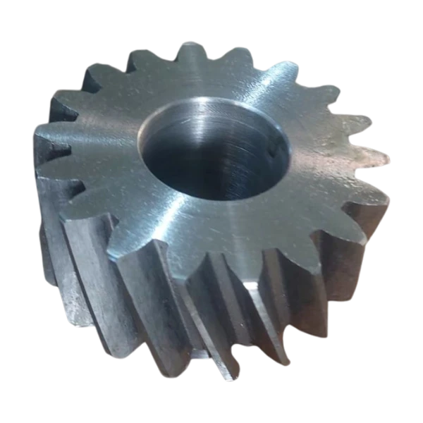
When should helical gears be considered?
| Information | Why is it needed? |
|---|---|
| Normal or transverse module | To define the intended tooth geometry correctly |
| Helix angle and hand | To assess meshing and axial thrust |
| Plane in which pressure angle is defined | To check compatibility with the mating gear |
| Centre distance and operating backlash | To define assembly conditions |
Material, machining and mating gear compatibility
Material and heat treatment depend on tooth contact loading, root stress, speed and duty cycle. Increasing face width alone does not establish even load distribution: shaft deflection, bearings and alignment also matter. If heat treatment is planned, subsequent finishing needs and the final condition of critical mounting features should be defined in advance. The relationship of the bore, keyway and end faces to the gear axis must be clear on the drawing.
Required data on a helical gear drawing
- Module, identifying whether it is normal or transverse, and the tooth count.
- Helix angle, right-hand or left-hand helix, and the plane defining the pressure angle.
- Face width, outside diameter, hub dimensions and any profile shift.
- Bore, shaft and keyway dimensions, tolerances and mounting reference features.
- Material, heat treatment, hardness zones and required finishing operations.
- Mating gear data, centre distance, operating backlash and inspection requirements.
Preparing a production enquiry
Frequently Asked Questions
Why is helix hand important?
Helix hand affects compatibility with the mating gear and the direction of axial force. Right-hand or left-hand helix should be stated on the drawing rather than inferred from a photograph. For replacement parts, the mating gear hand and the transmission arrangement should be checked together.
Does manufacturing accuracy eliminate axial thrust?
A single-helical gear generally produces axial force under load. Bearings and the housing must be assessed to support it. Selecting a helix angle changes the force balance, but manufacturing accuracy does not eliminate the axial force inherent in the geometry.
Are normal module and transverse module the same?
In a helical gear, they are defined in different planes and are related through the helix angle. Giving only a module value can lead to an incorrect interpretation. The drawing should identify its plane together with the pressure angle and helix angle.