

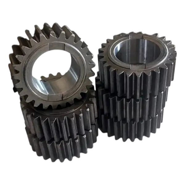
Which drives suit spur gears?
| Factor | What does it affect? |
|---|---|
| Module and tooth count | Size, ratio and nominal centre distance |
| Pressure angle and profile shift | Compatibility and tooth geometry |
| Face width | Load distribution across the tooth |
| Bore, keyway and reference face | Shaft connection and mounting position |
Material and machining decisions
Material selection should reflect the nature of the load rather than hardness alone. Tooth root strength, surface wear, shock loading and lubrication are considered together. Where heat treatment is required, the drawing should identify hardness zones and subsequent finishing needs. The machining sequence for the hub, bore and keyway belongs in the same plan. Because heat treatment can change dimensions, critical mounting features must be specified in their final condition.
Required information on a spur gear drawing
- Module, tooth count, pressure angle and profile shift coefficient where applicable.
- Face width, outside diameter, overall length and hub dimensions.
- Bore or shaft tolerances, keyway and the reference surfaces to be used.
- Material, heat treatment requirements, hardness zones and surface requirements.
- Mating gear dimensions, centre distance and required operating backlash.
- Quantity, drawing revision and functionally critical inspection features.
Requesting a quotation with a drawing or sample
Frequently Asked Questions
Are module and tooth count enough to manufacture a gear?
They describe basic geometry but are not sufficient on their own. Pressure angle, face width, profile shift, mounting dimensions and material are also required. For a replacement within an existing pair, the mating gear information and centre distance must be reviewed too.
Can measurements be taken from a worn spur gear?
A sample can be examined, but worn tooth thickness or a damaged bore should not be treated as a nominal dimension. Sound reference features, the mating gear and assembly dimensions are reviewed together. The aim is to define a functioning replacement rather than reproduce wear.
Does a spur gear generate axial force during operation?
In ideal spur gear geometry, there is no helix angle and therefore no axial component of the tooth force. Tangential and radial forces still enter the bearing calculations. Assembly errors and axial loads from other machine components must be considered separately.