

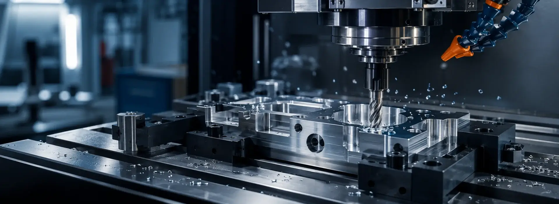
Functional Geometry Defines Precision
A precision CNC milling requirement is not defined only by a tight dimensional tolerance. The flatness of a mounting face, the position of a hole relative to datums or the orientation of two surfaces can determine how the part works. The drawing must clearly identify where these requirements apply. When separate dimensions function together in an assembly, the relationships between features matter alongside individual measurements.
| Drawing requirement | Information to clarify | Planning focus |
|---|---|---|
| Positional tolerance | Relevant datum system | Hole-to-reference relationship |
| Surface orientation | Referenced surface | Workholding and operation sequence |
| Form requirement | Area of application | Machining and inspection approach |
| Surface symbol | Functional surface boundary | Finishing requirement |
Datums and Workholding Sequence
The datum arrangement establishes how the part is located and how it is evaluated during measurement. Where reclamping is needed, the review considers whether critical features can be completed within the same reference system. Thin walls and small contact areas can increase sensitivity to clamping. Drawing requirements are therefore considered alongside stock form and available tool approach directions; the operation sequence is not assumed from the finished model alone.
- Measurement datums and their order of precedence
- Features with positional, orientation or form requirements
- Specific areas to which surface requirements apply
Surface Requirements and Measurement Planning
The Technical File for a Precision Milled Part
Frequently Asked Questions
What tolerance can be specified for precision milling?
Achievable tolerances are assessed alongside geometry, material, feature size, datums and operation sequence. A single general value cannot describe every component. The scope is established for the particular part against its drawing requirements.
How should a surface finish requirement be stated?
Use the appropriate drawing symbol and clearly identify the surface to which the requirement applies. Explaining whether the surface serves a mounting, contact or movement function also helps assess machining and inspection needs.
When should an inspection report be requested?
State the requested reporting scope during the quotation stage. Once the dimensions, geometric features and measurement references are clear, the inspection expectations and manufacturing scope can be considered together.